OneCNCXR8 Release 63.08
OneCNCXR8 Version release 63.06
Exciting new release of OneCNCXR8
OneCNC Users have been requesting this function and now we are pleased to deliver.
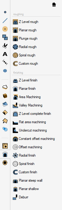
This release is a major release because includes the release of the new machining Deburr Functions. These new functions are available in the OneCNCXR8 Mill Expert mill versions. OneCNCXR8 Expert Version the Deburr function is in the model toolpaths
For users that have the 5 axis 3+2 function added to the OneCNCXR8 Mill Expert there is a new 5 axis Deburr function included on the 5 axis model toolpaths.
Deburr Overview
Deburr is a high-speed method of both programming and CNC machine deburring of modelled components.
Deburr ishould not to be confused with a chamfering function because chamfer is a different method using different tools.
Deburr is designed as an automated "deburr function" specifically using a “ball mill” and does not use a chamfering type tool or tapered tools.
Deburr function requires a "valid single model "and does not deburr "surfaces or geometry" style or STL parts because a model to have precise 3D edges to create the special 3D offsets required.
The model must be a valid single region model. OneCNC deburr can be used on multiple models but the models must not be touching and must be apart with sufficient tool machining clearance distance between the models or controlled by boundary.
The model should not be modelled with the “Deburr” distance already modelled on the model because the popular modellers that we have tested are not easily able to correctly model a deburr edge.
Models that are not singular valid models use other OneCNC machining functions to process those models.
OneCNC uses 3D spatial planar technology to correctly maintain the correct 3D offset to perform the constant deburr utilising a ball mill.
The Deburr video https://youtu.be/2bIhFDMZGpg shows examples of 3D spatial offset ability around 3D edges tapered and radial as well as holes and blind edges.
OneCNC installation includes 2 sample models in the OneCNCXR8 samples directory one for 3 axis deburr and one for 5 axis deburr that were machined in our testing routines and include known difficult 3D offset edges. You can see in those samples what is required in 3D spatial offset to perform the deburr with precision automatically.
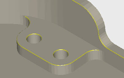
This graphic shows a typical difficult edge to deburr.

Because the Deburr is generally only required to be 0.15mm deburr (.006 in) it has to be accurate to perform correctly because it is so easily seen if it is not correct.
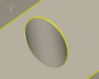
For example deburring a hole on a tapered wall the 3D Spatial offset is infinitely changing the offset all the way around the perimeter of the hole.
This graphic shows the deburr around the edge of an angled hole.
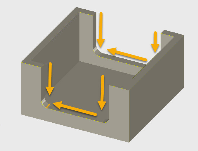
When machining a deburr directional control is predominantly the shortest path with control logic on edges that contain vertical moves to ensure that the deburr is performed always in the down direction to prevent tool breakage which would happen on up moves on vertical edges. Due to this the edges are performed bidirectional rather than climb milling. Exhaustive practical tests were carried out to ensure the best bidirectional methods and due to the tool size compared to the deburr distance amount using high spindle speed.
Deburr Settings
Deburr settings have been automated and simplified and all that is required is the tool size and the deburr distance. The distance between deburr and blind ends or bosses and other parts of the model are fully automated together with the finish tolerance.
The most popular deburr setting distance is 0.15mm (.006 in) using a 3mm ball mill (.125 in) or smaller.

The smaller size tool is preferable because it allows deburr closer to blind ends.
The deburr amount is restricted to .25% of the tool diameter. This is mainly due to guiding the preferred use of deburr distance to prevent excessive deburr size to defeat the purpose of deburr. Using small tools and high-speed passes requires minimum deburr distance to prevent tool breakage.
Typical deburr setting using would look like this

The deburr edges can be individually selected just by cursor clicking the edged or use one of the automated methods of part or boundary control.
There is another major addition to OneCNCXR8 in this release.
DWG/DXF
OneCNC has developed a complete new DXF and DWG import export function for OneCNCXR8. Continuing our ongoing development for the Industry 4.0 standard.
OneCNCXR8 Version 63.08 is now available in the OneCNC File Manager.
OneCNC Updates
OneCNCXP 5.23
Jul 31 2003
OneCNCXP 5.27
Sep 05 2003
OneCNCXP 5.29
Sep 12 2003