OneCNC Series Updates

This is a history of all OneCNC updates.

You may notice sometimes there can be a jump in version numbers.

This is due to intensive and continual internal testing where we thoroughly test versions before releasing proven functional updates.


To download updates, see our OneCNC Updates page.

OneCNCXR3 11.08

Contents of Update 11.08

This ONLY applies to OneCNCXR3 Lathe Professional and OneCNCXR3 Lathe Express

Modifications were made to the added Mill Turn modules C Y and B to allow the functionality of G17 and or G19 for the Y and B axis. To simplify the post setting a new setting has been included in the Multi Axis tab in the post.

Read More...

OneCNCXR3 11.02

IF YOU HAVE OneCNCXR3 NETWORK VERSION DO NOT INSTALL V11.02 UPDATE UNLESS YOU HAVE A NEW CDKEY FOR THE SERVER AND A NEW SERIAL FOR THE SERVER
_______

WENN SIE MIT EINER OneCNCXR3 NETZWERKVERSION ARBEITEN, INSTALLIEREN SIE V11.02 NICHT BEVOR SIE EIN NEUES PASSWORT FÜR DEN SERVER ANGEFORDERT HABEN


The server and serials only apply to the server software and not to the product software or product serials.

Contents of Update 11.02

New OneCNC Server Version 2.02
The OneCNC had been re-developed to allow more licensing flexibility and to handle future releases. There is an issue where the new server software requires new serials and a new CDkey for installation. This only affects OneCNCXR3 Network users and only version 11.02 and later.

Simulation/Rest
All milling and lathe versions have had a benefited from our extensive optimization of our Simulation/Rest functionality. These have benefited both from speed increase and tolerance refinement. Rest material now starts showing from 0.15mm increasing in yellow color then becomes orange right through to red and then deep red.

Lathe Mill Turn
The Lathe mill turn Y axis module has had some refinement to lessen support and improve programming consistency. Arcs on the Y axis are now confined to R the same as the arcs for the wrap cycle defined only as R. The majority of controls Fanuc being the main one only accepts R for the wrap cycle and we have made the Y face the same in version 11.02

Read More...

OneCNCXR3 10.98

New release 10.98 10th February 2009 for all OneCNCXR3 Lathe Mill Turn versions

Contents of Update

There has been an adjustment made to the posting of Wrap cycles This was to eliminate a problem that could be encountered on the first move of the Wrap function applying a Y.

This version update only applies to Mill Turn and only to the Wrap Cycle. 


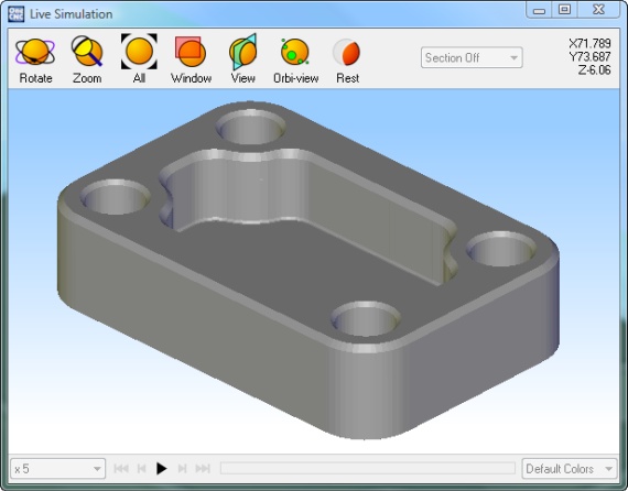
Overview of the new simulation and rest in OneCNCXR3 products

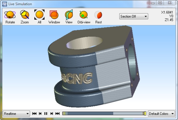
The new simulation now built into OneCNCXR3 now covers all Milling and Lathe products.
The simulation has been totally re-designed from previous OneCNC versions and now designed to handle all the standard 2 and 3 axis machines right through to and including the multi-axis and multi-function machines.

These are the following products that now have this functionality fully installed.

These are the milling products:
OneCNCXR3 Mill Express
OneCNCXR3 Mill Advantage
OneCNCXR3 Mill Professional
OneCNCXR3 Mill Expert
OneCNCXR3 Milling Professional and Expert 4 axis module
OneCNCXR3 Milling Professional and Expert 4 + 5 axis module

These are the lathe products:
OneCNCXR3 Lathe Express
OneCNCXR3 Lathe Express C axis live tooling module
OneCNCXR3 Lathe Professional
OneCNCXR3 Lathe Professional C axis live tooling module
OneCNCXR3 Lathe Professional C + Y axis live tooling module
OneCNCXR3 Lathe Professional C + Y + B axis live tooling module

Simulation Function

The main reason for the new simulation and rest was to handle Multi Axis which OneCNC has not had before.

The next reason was to have the added security of comparing the machined model with the original actual model which OneCNC did not have before. 

The simulation and rest comparing it to the original model is very hard to find in thCAD/CAM industry. OneCNC has always pioneered the simulation as OneCNC did back in year 2000 and in 2009 as a standard procedure we are comparing the machined model with the original model. This Model ability is what other CAM vendors dream about.

Purpose of "Simulation"
The primary purpose of the simulation is to allow the user to error check his machining against the original model that the machining was created from. The simulation and rest is not a replacement for a coordinate measuring machine but rather is an accurate guide to the machining processes to show the user the machined component and alert the user if the part is wrongly machined gouged or machining functions not performed. For checking accuracy of sizes it is recommended to use the simulation with geometry shown and have the geometry available of critical parts it is easily seen at that time. It is possible to zoom in and see with very good accuracy sizes.

Sectioning of Simulation:
This is now possible "Real-time" which can mean a saving of many hours in examination from all angles especially on large complicated components.

Rapid clearance plane moves:
Rapid clearance plane moves are only shown as an indication of the functionality and the direction of the moves. They are therefore only joined in a direct line manner. This is not a problem providing in OneCNC the rapid plane clearance is observed. This is to ensure that the clearance is set to be clear of any part projections or holding clamps etc for the applicable function. The reason for this which may be different from the actual machine clearance moves is because mostly rapid movers are completely machine action dependant. For example a G0 move for X0 Y0 to say X200 Y100 OneCNC will show this as a direct straight move whereas the machine would possibly have a dogs leg type move rather than a straight move. This is because there is a variation in the move amount of the X move compared to the Y move.

Coordinates indicator in simulation:
Coordinates are always indicated in an absolute X Y or Z which may be different than for the posted code. In the the case of lathe X movement it is always shown as a radius because again this indicator is not for part measurement but an axis indicator to assist in the observance of actual movements. Measurements of movements should be measures from the backplot function.

Accuracy of the simulation:
The simulation is very accurate and for checking purposed the user can turn on the construction geometry that he may have of actual size geometry and you can zoom in to a high degree of accuracy for visual checking. The middle default setting is usually all that is required to view simulation and speed should not be set above default ot it may become stepped due to PC power depending on the PC the user has. As the tool moved through the stock machining the component the machined model is being continually "live" modeled with this new simulation therefore trying to run it too fast for your PC will not give the best visual results. 

The simulation provides an accurate representation of the machining cusp shape and height of the tools and tool-path in the machining process and is a very good guide of how the finished part would be expected to look like. As explained earlier for checking accuracy of sizes it is recommended to use the simulation with geometry shown and have the geometry available of critical parts it is easily seen at that time. It is possible to zoom in and see with very good accuracy sizes.

Support for tools and tool holders:
The simulation supports all standard tools from the tool library. End Mill, Ball Mill, Bull Mill, 45 degree Chamfer cutters and drills and face mills are the only supported tools for simulation at this time.

All types of custom holders are supported and the drawings can be associated to the tools in the last column in the tool library. The simulation does not support custom shaped tools or center drills at this time. This is because the tool library does not have all the custom sizes for that type of requirement. Two diameter type Center drills are simulated at the major diameter and flat bottom for the length to indicate the tool position and length. There are too many variations of diameters and custom lengths due to sharpening etc to support at this time. We also notice a large number of users use spotter type drills for this anyway and those is supported with the standard drill library configuration. 


Speed of Simulation:
Providing the PC complies with suggested requirements and the slider bar is in the center or to the left of that the speed is very good considering the fact that OneCNC is now modeling the machining.

Tips on using the new simulation in OneCNCXR3

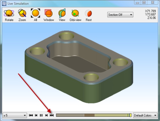
When using simulation and you want it to run turbo to the end without the tool action for fast simulation just click the two arrows rather than trying to drag the slider bar across. 

Rest Function

Purpose of "Rest":
The primary purpose of the "rest" is to detect un-machined areas of a part after machining.
For example if the part model has holes to be drilled and if the user has missed programming those they will be easily seen when running the "rest" function. The Rest now compares the machined model with the actual model which has not been done before. Previous versions of OneCNC only mathematically compared it to the expected size.

The purpose of the "rest" is not for measurement of part size but primarily just to indicate material that is still to be machined or has been missed or mistakenly removed. For checking of sizes it is recommended that you use the simulation only.

Accuracy of "Rest"
Due to the power availability of the present PC and the sophistication of part modeling indication of material left starts from approximately 0.5mm as a starting shade of yellow and continues in yellow shades until reaches 1mm and then gradually blends to becomes red. This is applicable to the complete part and includes all sides and the full shape in the case of multi axis machining.

As PC's become more powerful this margin may be reduced although tests prove that this small amount is enough to alert the user if it has been wrongly machined. The "rest" is certainly not a replacement for your measuring tools or your CMM machine but rather primarily to indicate parts left un-machined or incorrectly machined. We are continually working on optimizing code and have no doubt eventually there will be improvements in the tolerance because of speed improvements as well however it really does not change the way that it is meant to be used. For checking sizes it is recommended to use the simulation with geometry shown and if you have geometry drawn of critical parts it is easily seen at that time.

Speed of "Rest"
The rest is now in the simulation because OneCNC is now comparing the machined model to the original model  we have to machine it first and then run the Rest to do the Rest comparison.

Tips on using the new Rest in OneCNCXR3:
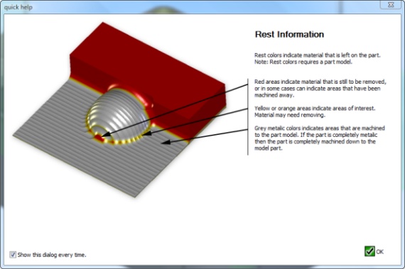
When you first use the rest you will see the following explanation dialog.


The new Rest as well as now being available in Multi Axis rather than being limited to 2 or 3 axis has changed from the OneCNCXR2/3 style to remove the in-accuracy of the OneCNCXR3 or the older XR2 style.

This was often caused because of a combination of colors that can vary depending on the graphics card and monitor and the method of determining rest. The big difference now is that OneCNCXR3 is directly comparing the machined model with the original model. This has not been done before. 

Previous "Rest"
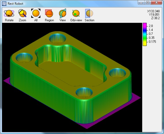
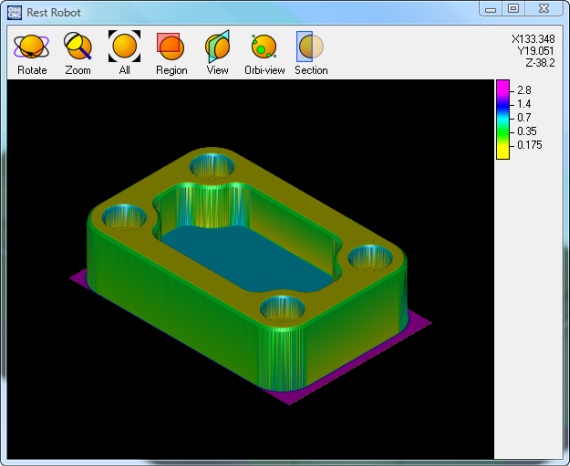
For example there is a sample in the samples directory that was also there in the previous OneCNCXR3 and if you run rest on it and although it is fully machined it shows variations if using the color guide of .35 up to 1.4mm which often caused confusion with users. Although it has always only been a guide rather than a measuring tool often users would have to double check.

The range of colors was also not suitable and we wanted to eliminate the problems for those with color eyesight deficiencies.


In the new rest starting at.5mm the shades of yellow get greater until it is shades of red at 1mm or the equivalent in Inches. Exhaustive testing proved that just the 2 colors and shades thereof proved beyond doubt the best combination.

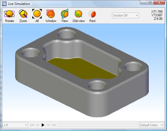
The new simulation and then rest because its fully machined it shows all grey and no shades of yellow or red. This eliminates the confusion and the user knows that not machining functions are missing and there are no gouges or parts wrongly removed. 


If the part has not been machined to size the color will show starting at .5mm like this next picture.

The previous rest was like this and the maze of colors caused some confusion to some users.

Read More...